TUIO 2.0 Protocol Specification
Martin Kaltenbrunner, November 16th, 2014
thanks to the valuable support by the participants of the TUIO Hackathon at ITS 2014 the TUIO 2.0 specification is now complete.
although the overall document may be restructured with some details for further clarification, the present specification is now considered stable and ready for implementation. an initial C++ reference implementation is now also available on github.
Introduction
This document defines the an abstraction framework, which shall meet the requirements for the comprehensive description of state-of-the-art tangible interfaces and multi-pointer surfaces. For that purpose we define an extensive protocol that allows the encoding and transmission of a tangible interface component abstraction, such as tokens, pointers and geometries as well as additional symbols and controls in the context of an interactive surface. The protocol extends and replaces the original TUIO specification, therefore the reader should be familiar with the general idea and structure of the previous TUIO 1.1 protocol generation. As in its predecessor, the TUIO 2.0 components and attributes are encoded using the Open Sound Control (OSC) format.
This protocol version introduces many additional features compared to TUIO 1.1. This includes timing information, several additional component attributes such as finger pressure, and code descriptors for symbol types such as data matrix labels or RFID tags. TUIO 2.0 also defines the precise object geometry with general bounds, contour and skeleton descriptors which can be used to describe untagged tangible objects or retrieve additional geometry information for tokens or pointers. Many syntactic changes have become necessary in order to define more OSC compliant messages and bundles, which together with the additional features should justify the version jump at the cost of backwards-compatibility at the protocol level. Future TUIO2 client implementations can provide additional backwards compatibility by implementing both TUIO 1.* and TUIO 2.0 protocol generations though.
Message Structure
TUIO 2.0 defines a unified profile for all previously covered tangible object types, such as tokens (tagged objects), pointers and geometries (for untagged generic objects). The idea of ALIVE and FSEQ messages of the original TUIO specification was generally maintained within /tuio2/frm and /tuio2/alv messages, while the SET messages of the previous 2Dobj, 2Dcur and 2Dblb profiles, were mapped to individual messages within the same /tuio2/* name space. Therefore the OSC name space was reduced to an abbreviated, but hopefully still human-readable structure and was also adapted to a more OSC compliant message and bundle style.
The distribution of SET messages over different profiles such as 2Dobj, 2Dcur and 2Dblb, has been reduced to dedicated TOK, PTR and BND messages that transmit the status updates for tokens (objects), pointers (cursors) and bounds (blobs). The component geometry can be described in greater detail with additional geometry messages such as OCG (contour) and SKG (skeleton). The new SYM messages allow the transmission of symbol content, and CTL messages allow the association of additional control dimensions to existing components. A set of associative messages allow the encoding of container relationships (COA) as well as mechanical or logical links (LIA) between physical objects. Custom messages that meet the requirements of yet undefined trackers now also can be realized within the same name space. This allows the usage of the same session ID across the same surface profile for alternative token, pointer or geometry references to the same tangible object. The specification primarily defines a profile for two-dimensional surfaces, which is partially extended to the 3rd dimension by complementary 3D component messages for tokens, pointers and bounds. Therefore TUIO was designed as a semantic description of tangible interfaces components within the confines of an interactive surface environment and the space expanding above that surface.
Please note: The following textual representation illustrates the syntax of the individual TUIO messages. An actual OSC implementation encodes these messages using binary data types, as specified in the attribute type table further below. You can also refer to the OSC specification for detailed information regarding the basic data types and overall message encoding.
Global Messages
FRM (frame message)
/tuio2/frm f_id time dim source
/tuio2/frm int32 ttag int32 string
The FRM message is a unique identifier for an individual frame, and therefore has to be included at the beginning of each TUIO bundle. Each frame is identified by a 32bit unsigned integer value that represents an incrementing frame ID. This allows dropping messages that arrive late with an eventually lower frame ID, the frame ID 0 is reserved as a default value for out of order execution.
The following time stamp is represented as an OSC 64bit time tag. Although the key component messages may include redundant speed and acceleration attributes that compensate for possibly lost packages, the availability of dedicated timing information is essential for many gesture-based interfaces. The dimension attribute encodes the sensor dimension with two 16bit unsigned integer values embedded into a 32bit integer value. The first two bytes represent the sensor width, while the final two bytes represent the sensor height. This allows to encode a sensor dimension up to 65535x65535 and implicitly also describes the surface ratio as well as its relative resolution. (In an optional 3D fishtank scenario - or the pointer hovering state - the optional Z-axis values are relative to the sensor height)
The source string attribute provides additional information about the origin of the TUIO message bundle. This string intends to provide a unique identification string for each TUIO source, which follows the following format convention: src_name:src_instance@src_origin, where the src name is provided as a unique and reasonably short identifier string for a TUIO server application, the src_instance numbers the various possible instances, while the src_origin encodes the machine address in HEX format, depending on its origin. So a single reacTIVision instance running on localhost could be identified by a source string in the form of "REAC", "REAC:0" or "REAC:0@0x7F000001" depending on its context. The TUIO2 client implementation needs to consider the correct decoding of the source string detail level.
ALV (alive message)
/tuio2/alv s_id0 ... s_idN
/tuio2/alv int32... int32
The end of each bundle is marked with the ALV message containing a list of all active session IDs, which allows the robust reconstruction of added or removed TUIO components. This is more robust than the possible usage of dedicated ADD or DEL messages, which can cause inconsistencies when lost on a transport channel such as UDP. Added objects can also be derived from their first appearance in a TOK, PTR or BND message. The session ID attribute is encoded using a 32bit unsigned integer value allowing a possible value range between 0 ... 4.294.967.295 until overflow, which should not cause any negative effects in a typical session. Since OSC only defines a default 32bit signed integer field, a TUIO implementation needs to cast the s_ID attribute to uint32 during the encoding/decoding step.
Component Messages
TOK (token message)
/tuio2/tok s_id tu_id c_id x_pos y_pos angle [x_vel y_vel a_vel m_acc r_acc]
/tuio2/tok int32 int32 int32 float float float [float float float float float]
The TOK message is the equivalent to the 2Dobj SET message of the TUIO 1.* specification, which encodes the common attributes of tagged physical objects. The Session ID (s_id) and Component ID (c_id) as well as the general X & Y position and angle attributes remain unchanged, while a combined Type/User ID (tu_id) allows the multiplexing of various symbol types within the same session as well as the association of an additional user ID. The first two bytes of the type/user attribute are therefore encoding the User ID, while the second half of the attribute encode the actual Type ID resulting in two 16bit unsigned integer values. This allows a possible range of 65535 Type and User IDs. The User ID can be used to determine if a token is currently being held by a user, therefore the ID 0 is reserved for the "no user" state. A TUIO implementation has to consider this special usage of the int32 tu_id attribute with an according encoding/decoding step. Speed and acceleration parameters are optional and the client implementation has to consider the two possible message lengths.
PTR (pointer message)
/tuio2/ptr s_id tu_id c_id x_pos y_pos angle shear radius press [x_vel y_vel p_vel m_acc p_acc]
/tuio2/ptr int32 int32 int32 float float float float float [float float float float float]
The PTR (pointer) message the equivalent to the 2Dcur SET message of the TUIO 1.* specification, which encodes the common attributes of pointing gestures. The message syntax changed significantly compared to the original profile, in addition to the Session ID and its X & Y position, it defines a Component ID that allows the distinction of individual pointer components during a whole session. The provided angle attributes specify the Pointer's rotation angle as well as the shear angle relative to the horizontal surface plane. An additional BND message can be used to specify the more detailed extension of the pointer.
The radius attribute indicates a pointer's "region of influence" by specifying its action radius (encoded normalized to the sensor height). An additional pressure value in the range from 0..1 was added for the encoding of discrete or continuous surface pressure. Additionally a negative pressure value can be used to indicate a pointer that is not in touch with the surface, and therefore in a hovering state.
The Type ID attribute allows the distinction of different pointer input devices and is also used to encode the associated User ID. The first two bytes of the type attribute are therefore reserved for the User ID, while the second half of the attribute encode the actual Type ID resulting in two 16bit unsigned integer values. This allows a possible range of 65535 user IDs and type IDs. A TUIO implementation has to consider this special usage of the int32 tu_id attribute with an according encoding/decoding step.
TUIO2 defines a list of default Pointer Type IDs, where the ID 0 stands for an undefined or unknown pointer. The IDs 1-5 define fingers of the right hand starting with the index finger (index, middle, ring, little, thumb) followed by same sequence from ID 6-10 for the left hand. The default ID for an unknown finger is the right index finger ID 1. The ID range from 11-20 defines a small selection of common pointer devices (11 stylus, 12 laserpointer, 13 mouse, 14 trackball, 15 joystick, 16 remote). The ID range from 21-30 defines various body parts (21 right hand pointing, 22 right hand open, 23 right hand closed, 24 left hand pointing, 25 left hand open, 26 left hand closed, 27 right foot, 28 left foot, 29 head, 30 person). Any Type ID starting from 64 and above can be freely associated by the tracker implementation.
Speed and acceleration parameters are optional and the client implementation has to consider the two possible message lengths, please note that the pointer encodes the pressure velocity and acceleration instead of the rotation values here.
BND (bounds message)
/tuio2/bnd s_id x_pos y_pos angle width height area [x_vel y_vel a_vel m_acc r_acc]
/tuio2/bnd int32 float float float float float float [float float float float float]
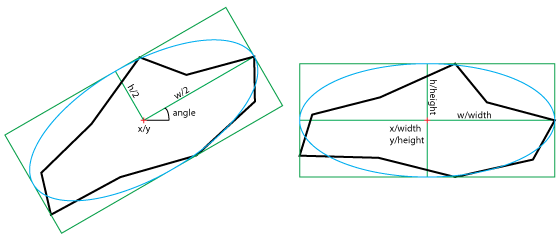
The BND message is the equivalent to the 2Dblb SET message of the TUIO 1.1 specification, which encodes the basic geometry information of untagged generic objects (blobs). The message format describes the inner ellipse of an oriented bounding box, with its center point, the angle of the major axis, the dimensions of the major and minor axis as well as the region area. Therefore this compact format carries information about the approximate elliptical region enclosure, but also allows the reconstruction of the oriented bounding box. The region area is normalized in pixels/width*height, providing quick access to the overall region size.
The BND message usually identifies the boundaries of any generic untagged physical object, and can be also used to transmit the basic geometry information such as the angle and dimensions of finger blobs or physical tokens that have been already identified by a previous PTR or TOK message. The session ID has to be equal in both messages in order to match the component with the corresponding bounds.
SYM (symbol message)
/tuio2/sym s_id tu_id c_id group data
/tuio2/sym int32 int32 int32 string string
The SYM message allows the transmission of the type and data contents of a marker symbol. Since this information can be redundant, and does not necessarily apply to all symbol types, it is represented by a dedicated message, which can be omitted or sent at a lower rate if desired. The Session ID, Type/User ID and Component ID are identical to the values used in the corresponding TOK message. Therefore the actual symbol code and the meta-information about the marker type and symbol description only needs to be received once by the client. The group attribute is a string describing the symbol type, such as fiducial markers, barcodes, or RFID tags. The code attribute is alternatively an OSC string or an OSC blob data field that transmits the symbol code or contents: such as the fidtrack left heavy depth sequence, an EAN barcode number, or an RFID UID. Since the possibly symbol space may often exceed the range of component IDs, a TUIO implementation needs to maintain its internal mapping of Symbols to Component IDs. In case a TUIO tracker such as an RFID reader, is not capable to determine the symbol position or orientation, the SYM message can be sent individually without any association to a previous TOK component.
|
/tuio2/sym 112 0 2 fidtrk/18 0122212221221221111 |
libfidtrack 18-node amoeba fiducial |
T3D (token 3D message)
/tuio2/t3d s_id tu_id c_id x_pos y_pos z_pos angle x_ax y_ax z_ax [x_vel y_vel z_vel r_vel m_acc r_acc]
/tuio2/t3d int32 int32 int32 float float float float float float float [float float float float float float]
The T3D message encodes an alternative 3D representation for tokens that are used within the space that extends above the surface. The message includes an additional Z coordinate as well as the rotation axis and angle. The optional velocity attributes also include these additional dimensions.
P3D (pointer 3D message)
/tuio2/p3d s_id tu_id c_id x_pos y_pos z_pos x_ax y_ax z_ax radius [x_vel y_vel z_vel r_vel m_acc r_acc]
/tuio2/p3d int32 int32 int32 float float float float float float [float float float float float float]
The P3D message encodes an alternative 3D representation for pointers that are used within the space that extends above the surface. The message includes an additional Z coordinate as well as vector of the pointing direction. The radius attribute refers to the spherical region of influence of the 3D pointer (encoded normalized to the sensor height).
B3D (bounds 3D message)
/tuio2/b3d s_id x_pos y_pos z_pos angle x_ax y_ax z_ax width height depth volume [x_vel y_vel z_vel r_vel m_acc r_acc]
/tuio2/b3d int32 float float float float float float float float float float float [float float float float float float]
The B3D message encodes an alternative 3D representation for untagged components that are used within the space that extends above the surface. The message includes an additional Z coordinate and the according depth attribute as well as the full 3D orientation axis and angle. The optional velocity attributes also include these additional dimensions.
Geometry Messages
The following list of CHG, OCG, ICG, SKG, SVG and ARG messages are optional descriptors of the component geometry, which can be incrementally describe the contour, skeleton and full area of the referenced component in various levels of detail. The RAW message allows in conjunction with an ARG message the full reconstruction of a bitmap that corresponds to the raw sensor data.
CHG (convex hull geometry)
/tuio2/chg s_id x_p0 y_p0 ... x_pN y_pN
The CHG message is a list of points that define the simplified convex hull of the blob. This means that the number of points has to be reduced to a reasonable amount, which represents the original hull with a minimum error. The client implementations have to take the variable length of this message into account.
OCG (outer contour geometry)
/tuio2/ocg s_id x_p0 y_p0 ... x_pN y_pN
The OCG message is a list of points that define the simplified outer contour of the blob. This means that the number of points has to be reduced to a reasonable amount, which represents the original contour with a minimum error. The client implementations have to take the variable length of this message into account.
ICG (inner contour geometry)
/tuio2/icg s_id x_p0 y_p0 ... x_pN y_pN true x_p0 x_p0 ... x_pN y_pN
The ICG message additionally defines the points of interior contour lines. According to the OCG message, a ring is only described as a disk, while the ICG message encodes the additional inner contour needed to reconstruct its full shape. The inner contour is a list of points that uses the Boolean value TRUE to indicate the beginning of a separate contour. A graphical representation of the number eight therefore would contain two inner contour sequences for example.
SKG (skeleton geometry)
/tuio2/skg s_id x_p0 y_p0 x_p1 y_p1 node ... x_pN y_pN
The SKG message represents the skeleton structure of a blob. In contrary to the list of contour points this needs to be represented as a tree structure. After the session ID the message begins with an arbitrary leaf of that tree structure and continues the point list until it reaches the next leaf point. The integer node number directs the tree back to the last node point.
S3D (skeleton 3D geometry)
/tuio2/s3d s_id x_p0 y_p0 z_p0 x_p1 y_p1 z_p1 node ... x_pN y_pN z_pN
The S3D message represents the three dimensional skeleton structure of a blob. Apart from an additional Z-coordinate for each node, this message follows the same syntax as the standard skeleton geometry message.
SVG (skeleton volume geometry)
/tuio2/svg s_id r0 ... rN
The SVG message adds the radius to each skeleton point as defined by the SKG message. This allows an approximate reconstruction of the blob volume (encoded normalized to the sensor height) based on the skeleton, without the need of the more detailed contour description. This message is based on information from the SKG message and can therefore only be used meaningfully after decoding a previous SKG or S3D message.
ARG (area geometry)
/tuio2/arg s_id x0 y0 w0 ... xN yN wN
The ARG message is the most detailed shape description message and describes the full blob area as a list of spans. This is basically a run-length encoding with an initial span point and the following span length. The span list allows the complete reconstruction of the region area and its exact contour information.
RAW (raw message)
/tuio2/raw s_id width data
This final RAW region descriptor provides additional 8bits of data resolution for each point of the region as referenced by a previous ARG (area) message. The data attribute is an OSC blob field with a length according to the amount of region points, where the individual samples are represented by an 8bit unsigned integer value. The actual decoding of this message has to follow the order of the previous span list, which therefore only covers the discrete region point samples. The previous width attribute specifies the relative distance between two points in order to correctly reconstruct the amount of samples between the initial and final span points. Although this value can be also retrieved from the surface dimension attribute of the preceding FRM message, it is included here for the convenience of rapid access. The RAW message allows for example the transmission of gray-scale image data from a computer vision sensor or pressure maps that have been retrieved from an according pressure sensitive device.
Content Messages
CTL (control message)
/tuio2/ctl s_id c0 ... cN
/tuio2/ctl int32 bool/float ... bool/float
The CTL message can be used to transmit additional control dimensions that can be associated to an existing component instance, such as a token with an incorporated pressure sensor or for example. This (open length) list of variable float or boolean values, encodes each individual control dimension as discrete 0/1 bool or continuous floats in the normalized range from -1.0f ... 1.0f. A simple 3-button wheel mouse for example could be encoded using a CTL message with three boolean values for the discrete buttons and one additional float value for the continuous wheel after the initial session ID.
An array of 12 float attributes can for example encode the keys of a full octave in a small piano keyboard including key velocity. The association of the according CTL message to a previous TKN consequently allows the identification and localization of that physical keyboard component.
DAT (data message)
/tuio2/dat s_id mime data
/tuio2/dat s_id string string/blob
The DAT message allows the association of arbitrary data content to any present TUIO component. Apart from the common session ID, this message only contains an initial OSC string that defines the MIME type of the following data attribute, which can be either transmitted using an OSC string or OSC blob data type. Therefore this message is capable of encoding and transmitting textural or binary data such as business cards, XML data, images or sounds etc. The DAT message can be for example also used to transmit the actual data content of an RFID tag that has been referenced within a previous SYM message. Due to the likely limited bandwidth resources of the used OSC channel, this infrastructure is not suitable for the transmission of larger data sets. In this case the use of alternative transport methods is recommended.
|
/tuio2/dat 113 text/x-vcard {OSC string w/ ASCII vcard} |
business card in VCARD format |
SIG (signal message)
/tuio2/sig s_id c_id s_id0 ... s_idN
The SIG message allows the transmission of a trigger signal from a reference component to one or more TUIO components which are specified in the following list of session IDs. The Component ID specifies the type of signal allowing a possible range of 4.294.967.295 signal variations.
Association Messages
The following association messages reflect the established links within constructive assemblies as well as container associations within the physical domain. We provide a description of the resulting component relationships, which can be employed to describe mechanical or logical connections as well as the placement of a token within the confines of another physical object.
ALA (alive associations)
/tuio2/ala s_id0 ... s_idN
The initial ALA message lists all active components that are currently in an associated state. This is providing a mechanism in analogy to the ALV message structure, and allows the robust reconstruction of connection and disconnection events.
COA (container association)
/tuio2/coa s_id slot s_id0 ... s_idN
The COA message allows associating one or more components such as several tokens to be contained within another physical component such as an object described by its geometry. Container associations are established by providing lists of one or more associated objects, which also allow the reconstruction of individual association events. The first session ID specifies the container object with a following variable length list of the associated object session IDs. We also allow nested container relationships, which can be encoded using various subsequent container messages. The provided slot attribute determines the entry point of the associated components within the container.
LIA (link association)
/tuio2/lia s_id bool s_id0 l_id0 ... s_idN l_idN
The LIA message is used for describing the topologies of constructive assemblies comprised of physical objects that allow the establishment of direct mechanical connections between them. The explicit declaration of physical object connections can for example be employed for environments, which are not capable of reporting spatial object relations. Additionally these connector associations can be used to encode collisions of physical objects, without the need for the additional transmission of the detailed object geometries for later collision detection.The initial session ID specifies the reference object with a following variable length list of a ID tupel that lists all component session IDs that are connected to the reference component as well as a coupled Link ID which identifies the input and output ports. This link attribute is comprised of two 16bit unsigned integer values embedded into a single 32bit integer value, which specify the output port within the initial two bytes and the input port of the connected component within the last two bytes. Alternatively the link association can also be used to establish logical connections between individual components, the provided boolean value determines if the association is physical (true) or logical (false).
LLA (linked list association)
/tuio2/lla s_id type s_id0 l_id0 ... s_idN l_idN
/tuio2/lla int32 bool int32 int32 ... int32 int32
LTA (linked tree association)
/tuio2/lta s_id type s_id0 l_id0 s_id1 l_id1 node ... s_idN l_idN
/tuio2/lta s_id bool int32 int32 int32 int32 float ... int32 int32
These two additional messages allow the encoding of connections between several interface components using linked lists, tree structures or individual connection lists for the encoding of more complex topologies. The LLA (linked list association) message encodes consecutive chains of connected objects, while the LTA (linked tree association) message encodes tree structures in a format similar to the SKG (skeleton geometry) described above. The initial boolean type value determines if the association is physical (true) or logical (false). The Session ID and Link ID tupels are structured as defined in the LIA (link association) message specified above. The LTA node jump uses the float data type in order to allow its correct identification.
Custom Messages
/tuio2/_[attr] s_id [list of attributes]
/tuio2/_sxyPP s_id x_pos y_pos int float
The custom profile allows the transmission of custom shaped messages that can change the position, omit or add attributes as desired. The message name is composed out of an initial underscore character that indicates a custom message. The following characters can be freely chosen from the list of know attributes as shown in the table below. Additional undefined parameters can be added using wildcard P character in the profile name. The actual parameter type is defined by the OSC message itself. The purpose of the custom message within the TUIO specification is to allow the TUIO clients at least a partial decoding of custom messages. Since TUIO is based on OSC a TUIO source implementation also can choose to add undocumented freely named and formatted messages, which then of course cannot be decoded by any standard TUIO client. Therefore the custom message should be chosen if any known attributes are transmitted, be it only the common session ID. This at least allows the client to associate the unknown message to a known symbol.
/tuiox/[ext] s_id [list of attributes]
It is important that all implementations within the dedicated /tuio2/ name space follow the exact message syntax and attribute format as defined in this specification. Any modification of the existing message syntax could lead to a fragmentation of the protocol specification and will also cause unstable results with standard client implementations. Although TUIO 2.0 intends to provide a versatile mechanism for the encoding of a large variety of tangible interaction platforms, it is also probable that some individual application scenarios or hardware platforms might requite an extension to the protocol. In case the custom message structure described above might not meet the semantic needs of such an extension, we suggest the usage of a separate /tuiox/ name space for the definition of message extensions that are following the general TUIO paradigm. This most importantly includes the shared reference to a common Session ID. Custom client implementations can therefore be configured to listen to one or more custom message extensions, while standard client implementations remain unharmed.
Message extensions could for example encode the attributes of dedicated controller devices such as the Wiimote (e.g. /tuiox/wii) or the complementary description of the user's hand (e.g. /tuiox/hnd). TUIO 2.0 does not define the three-dimensional geometry of interface components, which also could be implemented within several /tuiox/ messages if required. This extension space can also serve as a staging platform for the future inclusion into subsequent versions of the standard protocol specification. For all other custom messages that are not following the general structure of the TUIO protocol, we suggest the usage of a completely separate OSC name space though.
Timing Model
The TUIO 1.* specification originally did not contain any explicit timing information. On the contrary TUIO 2.0 transmits a time code for each bundle at a resolution smaller than microseconds by including a dedicated OSC time tag attribute with each FRM (frame) message. This level of time resolution provides enough information for time based gesture analysis on the client side.
Because of the possible packet loss, the key component messages TOK, PTR and BND still define the optional speed and acceleration attributes. In analogy to the normalized coordinate system, TUIO2 defines a velocity vector and a simple method how to calculate the resulting velocity and acceleration values correctly. The movement velocity unit is defined by the displacement over the full length of the axis (also normalized to 0-1) per second. As an example, moving a finger horizontally across the surface within one second, results in a movement velocity of (1.0 0.0) The rotation velocity is defined as one full rotation per second. Therefore as an example, performing one object rotation within one second, results in a rotation velocity of 1.0. The acceleration values then simple are calculated as a function of speed changes over time (in seconds).
Attribute Types
This table describes all the attributes that have been used with in the messages listed above and defines their OSC data format and expected range. The single letter representation in this table is also used in the identification string of the custom message format.
|
Parameter description |
Short message format |
Custom message code |
OSC data type |
value range |
|---|---|---|---|---|
|
Session ID |
s_id |
S |
32bit integer |
uint32 0 ... 4.294.967.295 |
|
Component ID |
c_id |
I |
32bit integer |
uint32 0 ... 4.294.967.295 |
|
Type/User ID |
tu_id |
T |
32bit integer |
uint16 0 ... 65535 (x2) |
|
Frame ID |
f_id |
F |
32bit integer |
uint32 0 ... 4.294.967.295 |
|
Frame Time |
time |
t |
64bit OSC time tag |
sec/nsec |
|
Point Coordinate |
x_pos, y_pos, z_pos |
x y z |
32bit float |
0.0f ... 1.0f |
|
Angle |
angle |
a |
32bit float |
0.0f ... 2Pi |
|
Pressure/Hover |
press |
p |
32bit float |
-1.0f ...1.0f |
|
Motion Velocity |
x_vel, y_vel, z_vel |
X Y Z |
32bit float |
-n ... n |
|
Acceleration |
m_acc |
m |
32bit float |
-n ... n |
|
Rotation Velocity |
r_vel |
A |
32bit float |
-n ... n |
|
Rotation Accel |
r_acc |
r |
32bit float |
-n ... n |
|
Width |
width |
w |
32bit float |
0.0f ... 1.0f |
|
Height |
height |
h |
32bit float |
0.0f ... 1.0f |
|
Depth |
depth |
d |
32bit float |
0.0f ... 1.0f |
|
Area/Volume |
area/vol |
f/v |
32bit float |
0.0f ... 1.0f |
|
Link ID |
l_id |
L |
32bit integer |
uint16 0 ... 65535 (x2) |
|
Source Name |
source |
N |
OSC String |
nx4 bytes |
|
Symbol Data |
data |
D |
OSC String/Blob |
nx4 bytes |
|
Data MIME Type |
mime |
M |
OSC String |
nx4 bytes |
|
Symbol Group |
group |
G |
OSC String |
nx4 bytes |
|
Node Jump |
node |
n |
32bit integer |
uint32 0 ... 4.294.967.295 |
|
Custom Parameter |
int, float, string ... |
P |
any OSC type |
Compact Message List
Global Messages
/tuio2/frm f_id time dim source
/tuio2/alv s_id0 ... s_idN
Component Messages
/tuio2/tok s_id tu_id c_id x_pos y_pos angle [x_vel y_vel m_acc r_vel r_acc]
/tuio2/ptr s_id tu_id c_id x_pos y_pos angle shear radius press [x_vel y_vel p_vel m_acc p_acc]
/tuio2/bnd s_id x_pos y_pos angle width height area [x_vel y_vel a_vel m_acc r_acc]
/tuio2/sym s_id tu_id c_id t_des data
/tuio2/t3d s_id tu_id c_id x_pos y_pos z_pos angle x_ax y_ax z_ax [x_vel y_vel z_vel r_vel m_acc r_acc]
/tuio2/p3d s_id tu_id c_id x_pos y_pos z_pos x_ax y_ax z_ax radius [x_vel y_vel z_vel m_acc]
/tuio2/b3d s_id x_pos y_pos z_pos angle x-ax y-ax z-ax width height depth vol [x_vel y_vel z_vel r_vel m_acc r_acc]
Geometry Messages
/tuio2/chg s_id x_p0 y_p0 ... x_pN y_pN
/tuio2/ocg s_id x_p0 y_p0 ... x_pN y_pN
/tuio2/icg s_id x_p0 y_p0 ... x_pN y_pN true x_p0 x_p0 ... x_pN y_pN
/tuio2/skg s_id x_p0 y_p0 x_p1 y_p1 node ... x_pN y_pN
/tuio2/s3d s_id x_p0 y_p0 z_p0 x_p1 y_p1 z_p1 node ... x_pN y_pN z_pN
/tuio2/svg s_id r0 ... rN
/tuio2/arg s_id x0 y0 w0 ... xN yN wN
/tuio2/raw s_id width data
Content Messages
/tuio2/ctl s_id c0 ... cN
/tuio2/dat s_id mime data
/tuio2/sig s_id c_id s_id0 ... s_idN
Association Messages
/tuio2/ala s_id0 ... s_idN
/tuio2/coa s_id slot s_id0 ... s_idN
/tuio2/lia s_id bool s_id0 l_id0 ... s_idN l_idN
/tuio2/lla s_id bool s_id0 l_id0 ... s_idN l_idN
/tuio2/lta s_id bool s_id0 l_id0 s_id1l_id1 node ... s_idN l_idN
Custom Messages
/tuio2/_[attr] s_id [list of attributes]
/tuiox/[ext] s_id [list of attributes]
Bundle Structure
While the bundle structure in the original TUIO definition was mostly used to take most advantage of the usually used UDP packet size, TUIO2 proposes a more structured use of OSC bundles in order to allow more TUIO2 client implementations on generic OSC platforms.
The current TUIO message structure used a single name space for all messages within a bundle, which eventually caused problems with some OSC implementations. TUIO2 already takes this into account with its newly defined message structure, and it also defines some simple rules for the internal order of each OSC bundle.
Each bundle needs to contain at least a FRM and a ALV message, where the FRM message is the first message in a bundle, while the ALV message concludes the bundle. As proposed in the original TUIO 1.0 specification, an implementation should take advantage of the full UDP packet size by creating message bundles that fit into the available packet space. Eventually free packet space can be filled with redundant object messages that can be periodically resent. It is up to the client implementation to identify and filter redundant messages.
In the following we are illustrating an example bundle encoding three active interface components including a tangible token with an associated symbol, a finger pointer with an associated basic geometry as well as an untagged tangible object specified by its basic geometry and outer contour. The full bundle is embedded within an initial frame message and the concluding alive message. Please note that the alive message is also containing an additional reference to an active component that has not been updated within this frame.
initial frame message
/tuio2/frm 1236 {OSC time tag} {640x480} REAC:0@0x7F000001
tagged physical token
/tuio2/tok 10 0 4 0.460938 0.3375 0.0 -0.0735294 -0.0980392 0 -0.450548 0.0
/tuio2/sym 10 0 4 fidtrk/18 0122222212221211111
touch pointer
/tuio2/ptr 12 1 0 0.525 0.3 0.05 0.0 1.0 -0.0781268 -0.104167 0.60428
/tuio2/bnd 12
untagged object geometry
/tuio2/bnd 11
/tuio2/ocg 11
concluding alive message
/tuio2/alv 10 12 11 14
Server & Client implementations
A TUIO server (sometimes also referred as TUIO tracker or TUIO source) is a device or application that encodes and sends TUIO messages based on the OSC format, while a TUIO client is an application or library that receives and decodes these messages, providing the basic infrastructure for an actual interactive application. This is actually the exact opposite of the OSC naming convention, where an OSC client is sending its messages to an OSC server, which usually means that a controller device (client) is attached to a synthesizer (server). Although this difference might cause some confusion, we think that our definition of TUIO servers and clients is more adequate for describing the direction of the data flow from the tangible interaction hardware to the application layer.
For speed and simplicity reasons, the TUIO protocol is generally unidirectional, which means that there is currently no dedicated communication channel from the client to the server necessary. Using the UDP transport for example, a TUIO server usually sends its messages to a single TUIO client, which can be running on the same platform as the server (localhost) as well as on a local IP network (LAN) or even at a distant location via the Internet (WAN). Nevertheless the present TUIO protocol could be equally implemented in a bi-directional configuration, where the application layer is sending standard TUIO messages to a tracker platform that is equipped with actuated components. In such a configuration TOK messages could be used for example to move physical objects or to drive actuated elements such as motors or lights with a sequence of according CTL messages.
A TUIO Server will usually encode and send messages for TUIO components that correspond to its general capabilities, therefore a server implementation can also choose to support only a subset of the possible TUIO components. Apart from the compulsory FRM and ALV messages, which comprise the basic body of a TUIO bundle, it depends on the server capabilities or configuration, which types of component messages are actually chosen to be sent. On the other hand a typical TUIO client implementation, especially if designed as a library component, should be ideally capable of decoding the full set of interface component messages as defined in this specification. We will provide TUIO server and client reference implementations for the most common programming languages, such as C++, Java and C#. These examples can be directly used as a library for the realization of TUIO enabled applications as well as a reference for the implementation for further programming environments. And since TUIO is based upon the OSC specification any platform that already provides an OSC infrastructure, is consequentially also able to send and receive TUIO messages.
Transport method
The default transport method for the TUIO protocol is the encapsulation of the binary OSC bundle data within UDP packets sent to the default port 3333. This default transport method is usually referred as TUIO/UDP, and most implementations are based on this method due to its simplicity and speed when sent over a network. Since OSC is not directty bound to a dedicated transport method, alternative transport channels such as TCP can be employed to transmit the OSC encoded TUIO data. As introduced with the TUIO 1.1 implementations, there are already several alternative transport methods available, such as TUIO/TCP and TUIO/FLC (flash local connection via shared memory) to interface with Adobe Flash applications for example. Due to the OSC encoding, TUIO messages can be basically transmitted through any channel that is supported by an actual OSC implementation.
A UDP packet can carry a maximum of 64kb and a minimum of 576 bytes, which usually provides enough capacity to transmit a typical TUIO bundle within a single UDP packet. When sent over a local or wide area network it is also advisable to limit the UDP packet size to the MTU size (usually about 1500 bytes) in order to avoid packet fragmentation. Therefore a TUIO server implementation has to consider that bundles containing larger component sets can eventually exceed the UDP packet capacity, and consequently need to distribute the component messages over several OSC bundles containing the same initial FRM message, while only the last bundle is concluded with a final ALV message.